SMA RF Connectors

Straight · right-angle / male · female / standard · reverse polarity — full-spec one-stop selection, DC–26.5 GHz RF interconnect solutions.

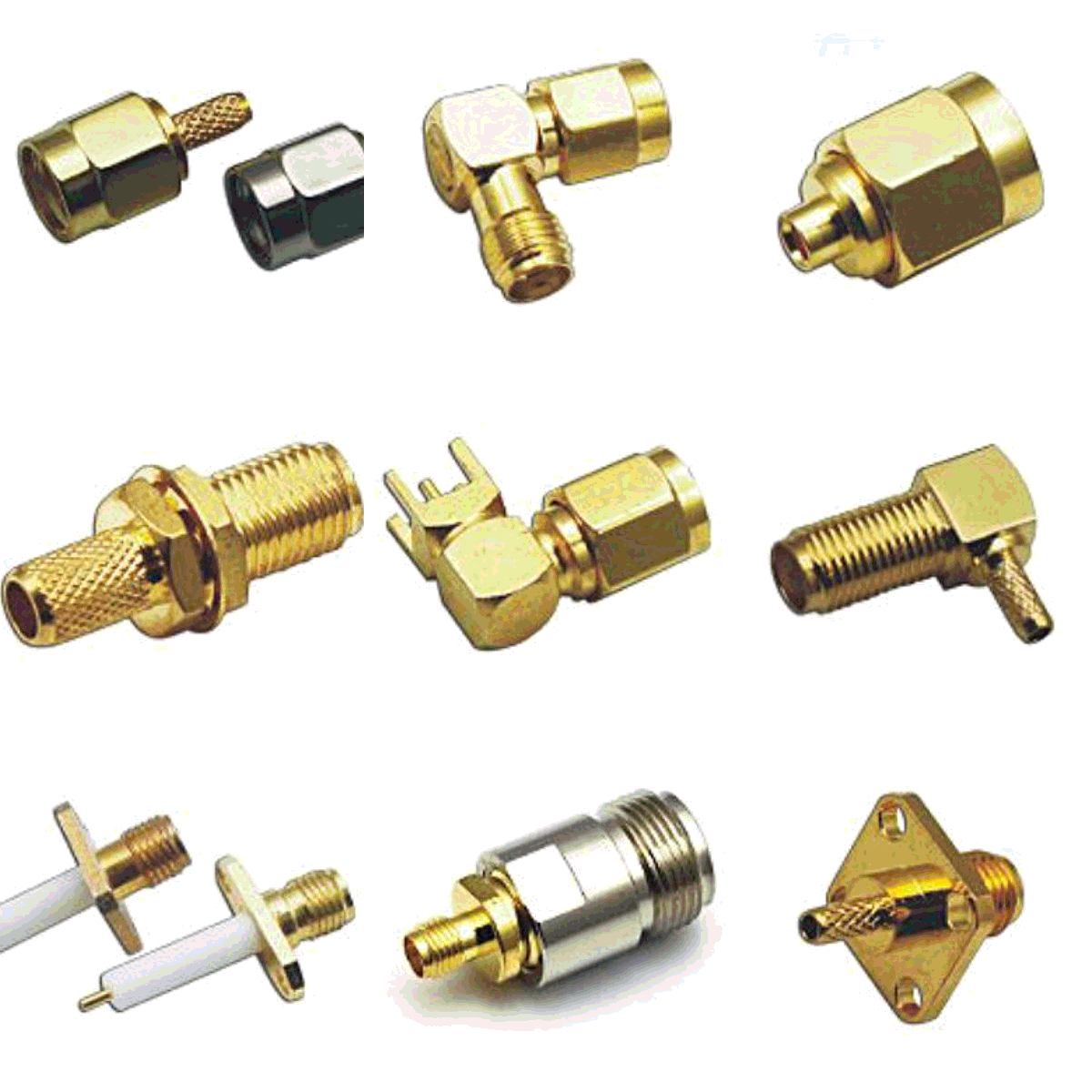
SMA RF connector product photo

SMA RF Connectors | Full-Spec Selection Guide

Straight / Right-angle · Male / Female · Standard / Reverse Polarity · DC–26.5 GHz

§1 Product Overview

SMA (SubMiniature version A) is a 50 Ω threaded RF coaxial connector developed in the 1960s by Bendix / Omni-Spectra, using 1/4-36 UNEF threads. Its excellent electrical performance and compact size make it widely used in test & measurement, satellite communications, 5G base stations, and Wi-Fi RF front ends. This page summarizes all SMA variants—straight / right-angle, male / female, standard / reverse polarity (RP-SMA), and PCB-mount—to help you select from a single page, with product photos and dimensional tables.

§2 Specifications

Parameter
Typical value
Frequency range
DC – 18 GHz (standard) / DC – 26.5 GHz (precision)
Characteristic impedance
50 Ω
VSWR
≤ 1.25 @ 18 GHz
Insertion loss
≤ 0.15 dB @ 18 GHz
Power rating
100 W @ 25 °C (1 GHz)
Operating temperature
−55 °C ~ +165 °C
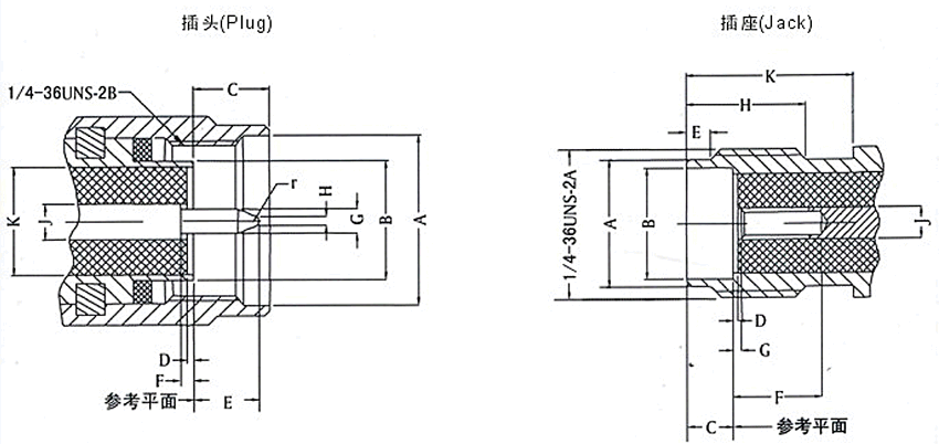
SMA interface mechanical drawing

§3 Product Catalog & Dimensions

Below are Coaxwave’s standard SMA connector photos and interface dimensions. All dimension labels correspond to one mechanical drawing set (Plug / Jack), in millimeters. PCB-mount variants add solder tails to the standard interface for vertical or horizontal board mounting.

SMA Interface Dimension Labels

The left drawing shows the plug (male) structure; the right shows the jack (female). Labels A through K are tabulated in each product card below.

SMA RF connector mechanical drawing: Plug and Jack

Standard Connectors

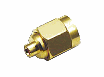
SMA male straight connector

Male · Straight

Standard / Cable termination

Straight plug with pin center conductor for RF cable termination or equipment panel output; coupling nut has internal threads.

DimMin mmMax mm
A6.35
B4.534.59
C2.563.43
D00.18
E1.912.56
F00.25
G0.900.94
H00.38
J1.251.30
K4.104.13

A is a minimum guaranteed length; no upper limit.
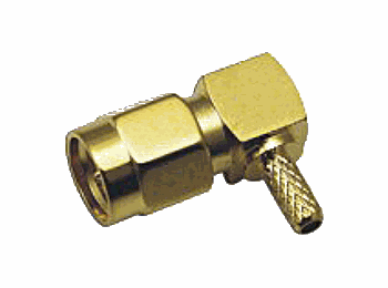
SMA male right-angle connector

Male · Right-angle

Standard / Cable termination

90° right-angle plug for chassis internal wiring or panel-against-wall scenarios, saving normal-direction space.

DimMin mmMax mm
A6.35
B4.534.59
C2.563.43
D00.18
E1.912.56
F00.25
G0.900.94
H00.38
J1.251.30
K4.104.13

Interface dimensions match straight plug; bend direction can be customized.

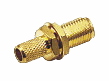
SMA female straight connector

Female · Straight

Standard / Panel mount

Straight jack with socket center conductor and bulkhead nut, commonly used for panel mount or cable termination; body has external threads.

DimMin mmMax mm
A5.285.49
B4.604.67
C1.881.98
D00.18
E0.381.41
F2.92
G00.08
H4.32
J1.251.30
K5.54

F, H, K are minimum guaranteed dimensions; bulkhead length can be customized.

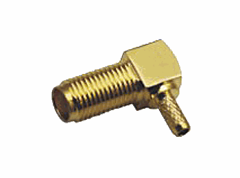
SMA female right-angle connector

Female · Right-angle

Standard / Cable termination

90° right-angle jack for dense cabinet internal wiring; cable exits perpendicular to the connector axis.

DimMin mmMax mm
A5.285.49
B4.604.67
C1.881.98
D00.18
E0.381.41
F2.92
G00.08
H4.32
J1.251.30
K5.54

Interface dimensions match straight jack; bend direction can be customized.

PCB-Mount Connectors

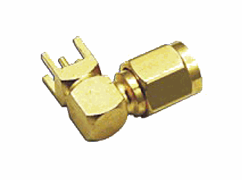
SMA male PCB-mount right-angle connector

Male · PCB-mount RA

PCB / Solder

90° right-angle PCB-mount plug with solder tails for direct attachment to RF front-end boards, used as antenna ports or test points.

DimMin mmMax mm
A6.35
B4.534.59
C2.563.43
D00.18
E1.912.56
F00.25
G0.900.94
H00.38
J1.251.30
K4.104.13

Interface matches standard plug; solder-tail pitch and length can match PCB layout.

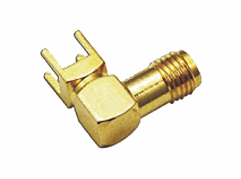
SMA female PCB-mount right-angle connector

Female · PCB-mount RA

PCB / Solder

90° right-angle PCB-mount jack, commonly used as a Wi-Fi / Bluetooth module antenna seat, supports horizontal or vertical soldering.

DimMin mmMax mm
A5.285.49
B4.604.67
C1.881.98
D00.18
E0.381.41
F2.92
G00.08
H4.32
J1.251.30
K5.54

Interface matches standard jack; solder-tail form and ground-pin count can be customized.

§4 Straight / Right-angle

Straight

The connector axis is coaxial with the cable, giving the lowest straight-through loss. Ideal for equipment panels and cable interconnects where space is ample and insertion loss is critical — e.g. VNA test leads and base-station RF links.

SMA straight connector

Right-angle

The connector axis meets the cable at 90°, saving internal chassis space. Suited to high-density racks, wall-mounted panels and constrained routing — at the cost of slightly higher insertion loss than a straight part.

SMA right-angle connector

§5 Male / Female

Male / Plug

Pin centre conductor with an internally threaded coupling nut. Typically used as an equipment panel output or cable-termination plug, screwing into a female for a locked joint.

SMA male interface

Female / Jack

Socket centre conductor with an externally threaded body. Used for cable termination or panel input ports, accepting a male plug to form a well-shielded coaxial channel.

SMA female interface

§7 Applications

VNA Test & Measurement

RF cables for vector network analyzers, DC–26.5 GHz; precision grade for de-embedding and calibration.

Satellite Communications

On-board and ground-terminal RF links across L / S / C bands, using standard-polarity male/female screw-lock joints.

5G Base-station RF Front-end

AAU / RRU RF ports and clock distribution; miniaturised high-frequency precision interconnect.

Wi-Fi External Antennas

Routers / gateways mostly use RP-SMA (reverse polarity) to prevent mis-insertion into standard-polarity equipment.

§8 Selection Guide

Space-constrained / High-density

Internal chassis wiring, wall-mounted panels → choose right-angle; 90° exit saves space at the cost of slightly higher loss.

Wi-Fi / Anti-misinsertion

Router external antennas → choose reverse-polarity RP-SMA; the swapped pin/socket design prevents mis-insertion into standard equipment.

Precision test / High frequency

VNA de-embedding, >18 GHz → choose precision-grade SMA (DC–26.5 GHz) for better VSWR and insertion-loss margin.

§9 FAQ

Q: SMA is rated 18 GHz — why does it still work at 20 GHz?
A: Return loss still has margin at the 18 GHz edge, but for 20 GHz+ we recommend precision-grade SMA (DC–26.5 GHz) to keep VSWR in check. See our article Why SMA rated 18 GHz still works at 20 GHz on a VNA.
Q: Can 50 Ω and 75 Ω SMA be mixed?
A: No. Impedance mismatch causes VSWR to degrade sharply and reflections to rise; use dedicated 75 Ω connectors. Measured data in What happens if you mix 50 Ω and 75 Ω SMA?.
Q: Can standard-polarity SMA plug into RP-SMA?
A: The threads match, but the centre pin/socket polarity is reversed, so after screwing in the inner conductors never make proper contact — plugged in but no signal. Wi-Fi antennas use RP-SMA to prevent mis-insertion.
Q: Can straight and right-angle be directly converted?
A: No. You need a matching SMA adapter or straight/right-angle cable; note that adapters add extra insertion loss.
Q: What is the difference between SMA and SMB / SMC?
A: SMA uses threaded coupling — more reliable and higher frequency; SMB/SMC are snap-on, suited to lower-frequency quick-connect scenarios.
Q: How do board-mount SMA and cable SMA differ?
A: Board-mount types have PCB solder tails, soldered directly onto the circuit board as an antenna seat or test port; cable types connect to coaxial cable via crimp or solder.
Sales@coaxial-rf.com · Get a quote

WeCom Online Consultation

Scan to add WeCom for SMA selection, lead time & quotes anytime
7×24 technical support & quoting

WeCom QR code